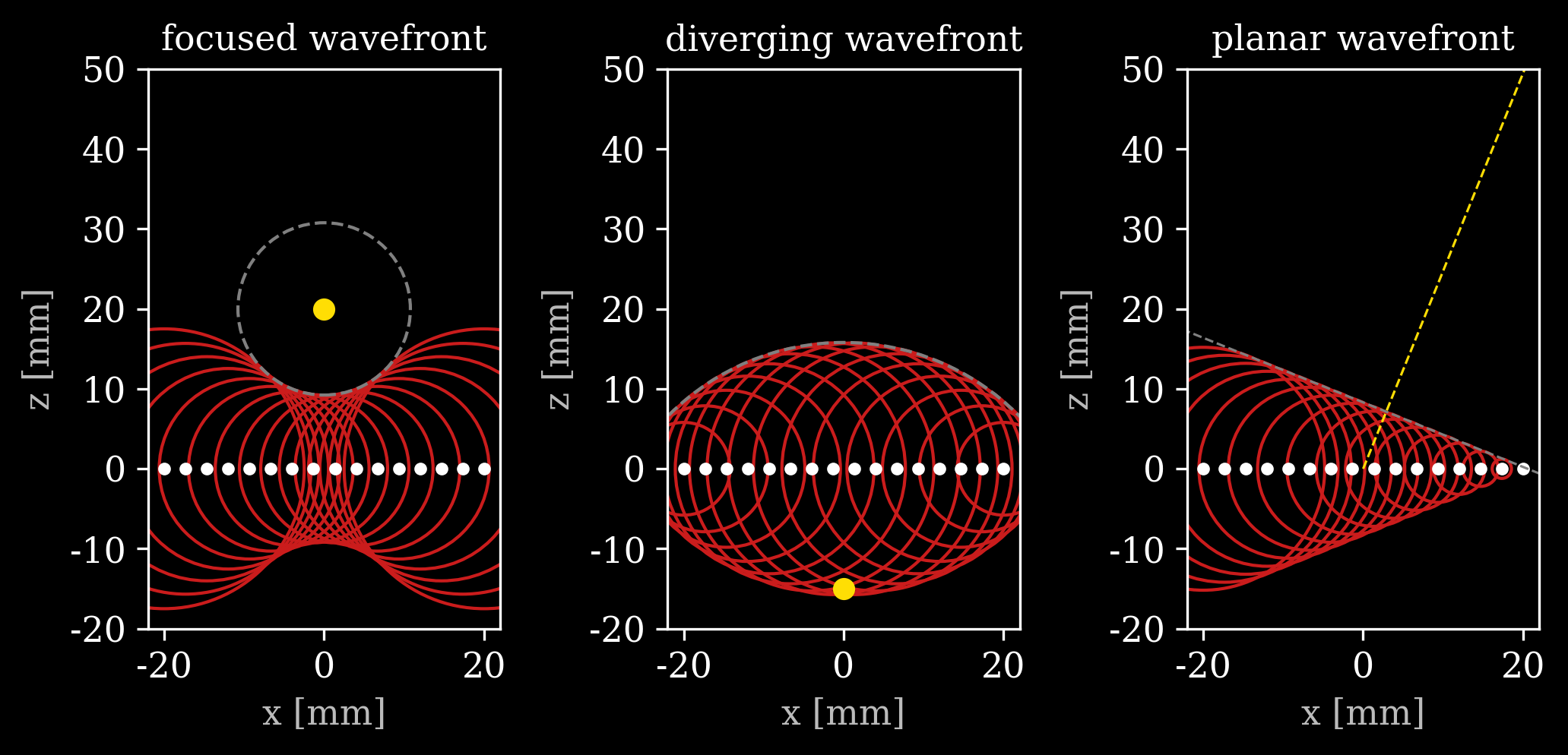
The shape of the wavefront that is transmitted is determined by the order in which the elements fire.
The image below shows the individual wavefronts emitted by the white elements for the three common transmit types: Focused wave, diverging wave, and plane wave.
- If we fire with delays such that all wavefronts pass through a focal point in front of the array at the same time we get a focused transmit wavefront.
- If we imagine a wavefront emanating from a virtual source point behind the array and fire each element when this virtual wavefront hits it we get a diverging wavefront.
- If we fire all elements with a constant delay between neighbors we get a planar wavefront.

You can play around with these plots in this interactive notebook:
Computing the transmit delays
To find the correct transmit delay for every element for every wavefront type we can imagine the desired wavefront already being there and coming in from behind the array. The elements will then fire when this imagined wavefront hits them.
Let’s assume we have an element at position and a speed of sound .
Focused transmit
For a focused transmit we define a focal point somewhere in front of the array. The virtual wavefront is a large circle around it that closes in to the focal point. Transducer elements that are far away are hit first. Being hit first means we have a negative delay with respect to other elements. The transmit delay of an element should therefore be
Diverging wave transmit
For a diverging wave transmit we define a virtual source somewhere behind the array and imagine a virtual wavefront emanating from it. The moment the virtual wavefront hits the element is just the time it takes to travel the distance to the virtual source. The delays can therefore be computed as:
Plane wave transmit
For a plane wave transmit we can imagine a straight wavefront coming in, moving in the direction (here we define to have unit length). The moment it hits each element is dependent on the projection of the position of that element onto :
We can add any constant time offset to the definitions in (1), (2), and (3) without affecting the wavefront shape as it is just the relative transmit times that are important.
The figure below shows an animation of how the wavefronts for the three transmit types are constructed from the individual element wavefronts. The virtual wavefront is shows as a gray dashed line. The virtual source/focal point is shown as a yellow dot or line.